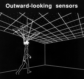

Figure 3.1 Conceptual diagram of optical tracking system. Diagram drawn by Mark Ward.
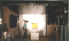
Figure 3.2 The actual system in operation
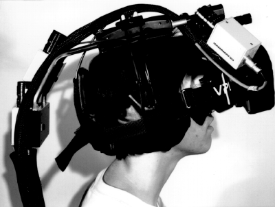
Figure 3.3 Side view of HMD equipped with four optical sensors
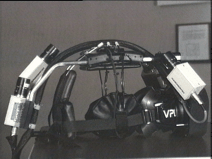
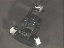
Figure 3.4 A pair of views of HMD equipped with four optical sensors
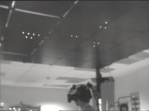
Figure 3.5 Lit LEDs in the ceiling
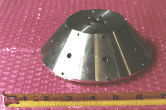
Figure 3.6 4-hat platform for mounting optical sensors
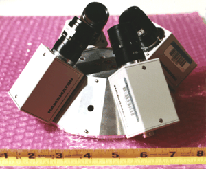
Figure 3.7 4-hat equipped with four optical sensors
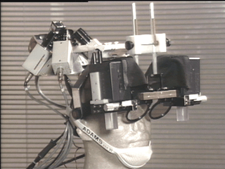
Figure 3.8 Front view of optical see-through HMD with 4-hat
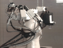
Figure 3.9 Rear view of optical see-through HMD with 4-hat

Figure 3.10 4-hat with probe attached
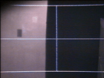
Figure 3.14 Actual view of crosshair, as seen inside the HMD
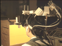
Figure 3.17 External view of boresight
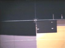
Figure 3.18 Internal view of boresight
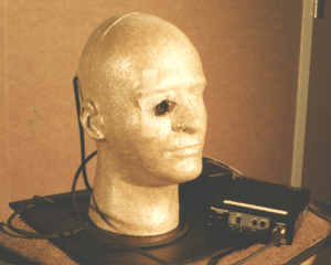
Figure 3.24 Bust with hole in right eye and video camera
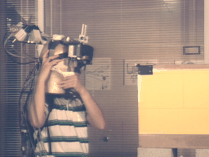
Figure 3.25 Carrying the bust with see-through HMD attached
 <.p>
<.p>
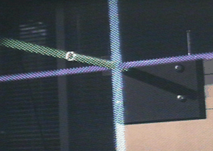
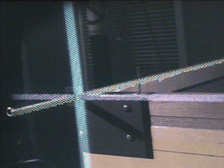
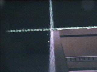
Figure 3.27 Views from static registration viewpoints #1-7 and #9
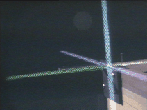
Figure 3.28 View from static registration viewpoint #8
Back to Ron's publication page